 |
 |
 |
 |
 |
 |
 |
 |
 |
 |
 |
 |
 |
 |
In this section, I want to explain the workflow in WonderBrush when doing some common tasks of graphics design. I will not zoom into details too far, like in the style "to create a new layer, in the Layer menu chose New". This would distract from the main description of the workflow too much and make this page a pain to read. Ok, now on for some examples!
Using Properties
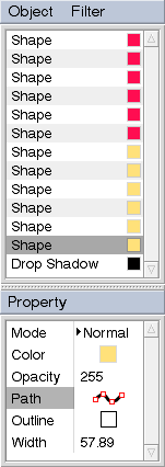
In this picture, I have created some Shape objects.

In the next step, I have copied the Shape objects behind the originals and toggled the Outline property for the clones. I have also changed the Outline Width, Color and Opacity property. This was only done to the first object, the rest was edited by copying and pasting the changed properties.
Now I have added a Drop Shadow filter object. The Outline Width property was changed again, as well as Color and Opacity. I also copied the original shapes once more, set their colors to white and made them less opaque. I moved these clones behind all other objects on the layer (by simple drag'n'drop) and added a Gaussian Blur filter in front of them. This adds a glow to the scene.

After all this work, I realised that I didn't like the shape of the "e" anymore. That was an easy change though, I just edited one of the copies of the "e" and because the Path is just another property, I could easily paste it to all other copies! 
I also realised I didn't like the glow too much, so I just removed all related objects. The Width, Opacity and Color of the outline shapes were also tweaked again. All these changes require just a few clicks. And it is all done on just one layer. |
|
|
Creating a Button

|

|
|

|
This example shows the usage of multiple layers to form a rendering pipeline for a button bitmap. Through the nondestructive editing possibilities this pipeline gives, any aspect of the button image can be changed later on. By simply changing the color of the Fill object on the bottom layer, the color of the entire button can be changed, the metallic effect and the bevel will simply be recalculated. Since all objects involved are based on vector data, the button image size can be changed without introducing any artifacts.
Here are step by step instructions for creating an image such as the one above.
 |
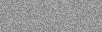
On the empty default layer, the Fill tool was used to create a grey Fill object. |
|
| ||
 |
A Noise filter was added, which was set to influence luminance only. |
|
| ||
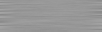 |
A Motion Blur filter was added with 90° direction and 30 to 40 pixel blur distance. |
|
| ||
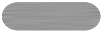 |
A new layer was created, on which a Brush object was added. A straight line
can be drawn by holding down the shift key when clicking the end point. The end
point can still be dragged as long as shift is held down. Clicking the
start point created a Brush object (just a dot), which we don't need, we
can delete that one. |
|
| ||
 |
The layer created in the previous step was duplicated. The Brush objects color was changed to white. Then it was duplicated. In the cloned Brush objects Property list, the rendering mode was changed to "Erase", and its Hardness setting was set to 0%. The Eraser object was translated with the Transform tool, so that the Brush behind it is only showing through at the left and top sides. The layers blending mode was set to "Luminance". The global alpha value of the layer was used to control its influence on the bottom layers. |
|
| ||
 |
The Luminance layer created in step 5 was duplicated and the Brush object was made black. The Eraser object was then transformed in the opposite direction, so that the black Brush can be seen at the right and bottom sides. The bevel effect is now finished. |
|
| ||
 |
The last layer was duplicated once again. The blending mode was set back to "Normal" and the Eraser object was deleted from it. The black Brush object was copied and turned into an Eraser object again. Then the original was scaled a bit to form an outline. The scaling can be entered numerically in which case the center of the transformation stays fixed. |
|
| ||
 |
The label was created from a Text object. |
|
| ||
 |
The Text object was duplicated two times, with the copies dragged behind the original. One of them was set to black, the other to white. Their opacity was lowered a bit so they blend with the background. To give the "edged in" effect, the copied Text objects were given a little offset from the original. |
|
